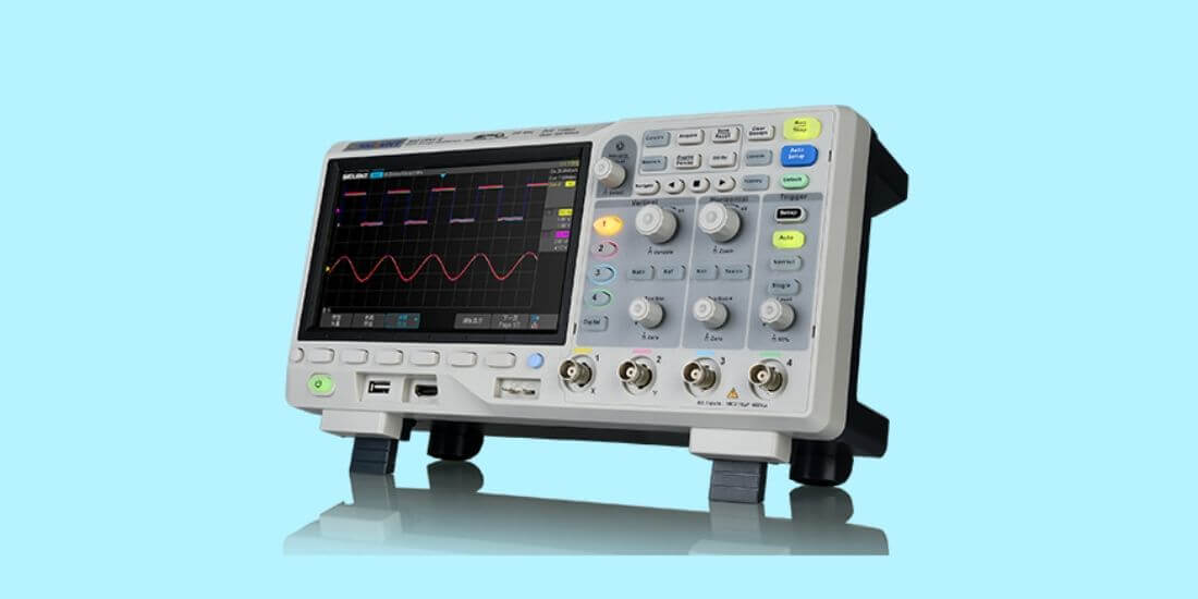
An oscilloscope is a powerful diagnosis and measuring tool for electric circuits. The advantage that an oscilloscope has over other measuring instruments is that it provides more information such as frequency, noise, and amplitude. It can also show you how a signal or value is changing with time.
However, at first glance, you might be overwhelmed by the hobbyist oscilloscope and have no idea how to operate it. There’s a lot to know about the oscilloscope and how it operates, but it’s a lot easier than you might think. This article will help you learn how to use an oscilloscope.
Oscilloscope Features and Uses
Before you go on to learn how to operate an oscilloscope, you should know more about the features of an oscilloscope and what it is used for.
An oscilloscope is mainly used to gauge the variation of an electrical signal with time. Not all signals or electrical inputs/outputs are static with respect to time.
Knowing how a signal changes and at what rate it changes is important. It is impossible to gauge the variation of a signal with a voltmeter. The oscilloscope is used primarily for the following applications:
Noise Detection
An oscilloscope can detect noise in your circuit or system. Noise is any unwanted signal that may cause the original message signal to be disrupted or distorted.
People working on their circuits will want to eliminate noise, but it is often difficult to do when large circuits tend to have many components. Oscilloscopes help to diagnose the source of unwanted signals.
Frequency and Voltage Determination
An oscilloscope can determine frequency and voltage values. Frequency is the number of times per second that a signal’s waveform or shape repeats itself.
Frequency is an important aspect of any signal. Being able to measure the voltage and frequency will allow you to detect whether a component is working properly or not.
Wave Shape Determination
An oscilloscope can determine the shape of the signal. Signals come in various shapes and have distinct properties.
Parts of an Oscilloscope
You should try to familiarize yourself with the constituents of an oscilloscope. There are some key parts you need to learn about beforehand. They are:
Related Guide: Oscilloscope under $1000 Review
The Display
This is where the output of a signal is shown. You’ll see a large screen on all oscilloscopes. The screen will consist of a grid and feature two axes. And the vertical or y-axis represents the voltage while the horizontal or x-axis represents time.
The display will show the signal’s shape, and from there, you can proceed to analyze or study the signal. It can also be used to display more signals depending on how many channels your oscilloscope has. This is an essential part of the oscilloscope, but its full potential is brought about by the other parts.
Control Board or Section
Besides the display, you will notice a selection of buttons and knobs on the face of the oscilloscope. Their placement varies between different oscilloscope models, but there are some common configuration settings amidst all models.
Channel and Source Selection Settings
These settings allow you to choose a source and, in turn, display the signal on the screen. If an oscilloscope has multiple channels, these settings will allow you to manipulate the channels to either have one or more of them displayed at the same time for comparison.
Trigger Settings
When you connect the oscilloscope to a component, either emitting the signal or through which the signal is passing through, you’ll notice that the signal is running. Electrical signals don’t stand still and keep varying over a certain frame.
It becomes difficult to measure a moving signal, but the oscilloscope has a built-in function that will allow you to solve this problem. A trigger knob in an analog oscilloscope allows you to set the trigger level.
The trigger level is the rate at which the electron beam that characterizes the signal in an oscilloscope moves from left to right. By adjusting the trigger knob, you can synchronize the horizontal sweep of the oscilloscope with the signal so that they move at the same speed.
What you’ll notice is that the running signal appears to look static. This is because the same frame is being repeated. It’s much easier to study a static waveform instead of a moving one.
Axes/Grid and Position Settings
There are two distinct sets of these knobs. One corresponds to the horizontal axis and one corresponding to the vertical axis. For oscilloscopes with more than one channel, there will be an equal number of sets for the vertical axis.
These knobs allow you to adjust the grid settings and allow you to change how much one division in the display represents. This is important in helping a person to measure the voltage and time period.
If the voltage of the signal is in the millivolt range, then you’ll be unable to even properly distinguish the signal if your knob is set to 2 volts per division. And if your signal has a large time period and you have your x-axis knob set to a small value per division, it might prove impossible to see if it is a repeating pattern.
Alongside the axes settings, there are also the position knobs. These knobs allow you to move the waveform up and down along the y-axis or left and right along the x-axis. And these allow you to move the waveform and study different parts of it.
Probe
An oscilloscope doesn’t display the signal by just being near its vicinity. You need some way to connect it to the component you want to measure or analyze the signal across. This is where the probe is needed.
Probes are input devices that provide a path through which the signal travels into the oscilloscope and gets displayed on the screen or display. They have a tip with a hook and an additional clip with which they can connect to the component.
Oscilloscope probes are special for a few reasons. The primary one being that these probes are made to ensure that no signal is absorbed by them or lost between transmissions. Probes are made to work even at high frequencies where other means of connections might suffer from signal losses.
Digital vs. Analog Oscilloscopes
Like other electrical instruments, the oscilloscope also has an analog version and digital version. A digital oscilloscope features a plethora of options that allow it to skip some of the initial tedium and difficulty of using an analog oscilloscope.
Some of these features include auto-calibration settings, auto setting the axes for the best picture, and auto-trigger settings. These allow an inexperienced person to handle an oscilloscope much more easily.
Alongside these, digital oscilloscopes feature greater specs such as being able to measure higher frequency ranges, greater sensitivity as well as more trigger options to tackle more complex waveforms with.
Learning how an analog oscilloscope works will also help you to get accustomed quickly to working on a digital oscilloscope. Much of the basics you tend to learn for the analog ones can be applied for the digital version with some options that can reduce tedium.
How to Use an Oscilloscope
All these steps are written for an analog oscilloscope. A digital oscilloscope has most of the same steps, with some being omitted due to having an automatic setting for it. The steps to using an oscilloscope are:
Setting up the Probe
Determine the number of probes you need. For the sake of simplicity, we will assume we are working with one probe. Make sure the probe’s attenuation setting is set to 1X (this is done by using the slider on the body of the probe with 1X and 10X written on the sides).
Connect the probe to any of the channels in the oscilloscope. Let us assume we have connected it to channel 1. Turn on the oscilloscope and set the source settings to channel 1 or auto. If you have done this correctly, you will see a straight line on the display.
And if the line is not appearing, you may have a disparity between the connection and channel settings.
Calibrating the Oscilloscope
Calibrating an oscilloscope is an important test as, without it, you might get wrong results and inaccurate values. The calibration procedure for a digital oscilloscope is often automated and can be done with the press of the right button. To calibrate an analog oscilloscope, there are some steps.
Determining Calibration Settings
On the oscilloscope, usually at the bottom, you’ll see a pin sticking out where the tip of the oscilloscope can be connected with. Underneath the pin, you’ll see writing that consists of a peak-to-peak voltage value and a frequency rating.
This is the built-in signal generator of the oscilloscope that is used for calibration settings and testing. When connected, you will notice that a square wave appears on the display.
Matching the Grid Settings
Pay attention to the ratings underneath the pin. If the ratings read 1 V p-p (1 Volt peak to peak) and 1KHz (1 Kilohertz), setting the x-axis grid settings to 1 millisecond per division (which is the inverse of the rated frequency) and set the y-axis grid settings on channel 1 (or appropriate channel) to 1 Volt per division.
Fix the Position
The square wave will change accordingly. Next, you need to use the position knob on the y-axis to move the square wave up or down until it touches the x-axis, making sure that no part of the wave crosses into the negative y-axis (below the x-axis).
You can choose to position the wave using the horizontal knob until the edge of the wave aligns with the y-axis.
Check if Voltage Is Calibrated
Provided you have properly aligned the waveform with the axes, measure the voltage of the signal.
You can do this by reading the peak of the square wave (since you have properly aligned the axes, just measuring the peak will suffice as the lower end is zero). Check to see if the value of the peak matches the voltage rating.
Check if Frequency Is Calibrated
Similarly, find the frequency of the square wave on the display. You can do this by finding the time it takes (from the x-axis) for the square wave to repeat itself. After finding the time, simply inverse the value. Check to see if the value matches the frequency rating.
If both the value matches, then your probe is working properly, and calibration is successful. And if the values don’t match, look for a smaller knob beside the grid setting knobs (or in some models, on top of them). Adjust those knobs until the values match with the ratings. Do not touch these knobs for the rest of your task.
If Calibration Doesn’t Work
In the case of a distorted wave appearing on the display, you might want to try a different probe or check to see if it is damaged or not.
Setting the Trigger Level
Once you have successfully calibrated the oscilloscope, remove the probe from the oscilloscope, and attach it across the component which you want to measure. It is recommended to connect it across the component with wires instead of directly connecting it.
When the probe is connected, you will begin to see a waveform on the display. Usually, this waveform will be running and hard to measure. You will want to adjust the trigger level knob until you see it begin to slow down until it stops entirely.
If the waveform isn’t stopping, you might want to set the time per division to a higher value and then try readjusting the trigger. Digital oscilloscopes have an auto-trigger mode that makes this process much smoother.
Measuring Values
Once the waveform is still, you can use the grid settings to magnify and get a better look at the readings. Digital oscilloscopes will often list the peak to peak voltages and time periods on the screen. Analog oscilloscopes can make use of the x-y mode to make taking amplitude readings much easier.
On the oscilloscope, you will see a trigger or button labeled x-y mode. What this does is that it turns your waveform into a vertical line.
The length of the line is the same as the length from the positive peak of the waveform to the negative peak.
You can find the amplitude of your signal by just dividing the length by two.
Recording the Waveform (For Digital Oscilloscopes)
Digital oscilloscopes often have means of saving the waveform in a usable file for future reference. This is done by using the hold option and then saving it. Some digital oscilloscopes feature an option to insert a USB drive and record the waveform in a file (usually PNG format).
Conclusion
Hopefully, you are now familiar with the ins and outs of an oscilloscope. While there are varying models with different features, this guide serves to give you the general gist of things and help you on your way. It will also help to read through your model’s instruction manuals for specific features and instructions.
-

One of the best ways to ensure the safety and efficiency of your electronics is…
-
Oscilloscopes are instruments used in the laboratory which is used to analyze waves of electronic…
-
Working with electrical appliances and designing flawless circuits is critical on its own. On top…
-
Whether you are a beginner or a professional, you will surely look for an oscilloscope…
-
An oscilloscope is a device used to view the voltage of an electrical component in…
-
If you have ever been to an electronics laboratory at your university, you have definitely…
-
Oscilloscopes are notoriously expensive. Whether you’re an enthusiast or a professional, you know how costly…
-
Gone are the days of using analog oscilloscopes to check your electronic equipment for faults.…